Manufacturing Notes - Process Science, Production Systems, and Engineering Decisions
This note is adapted from course materials for MNE3119 Manufacturing Technology at City University of Hong Kong. Instructor: course teaching staff.
Central Question
How do we transform uncertain raw matter into reliable products while controlling geometry, properties, defects, cost, throughput, safety, and environmental impact?
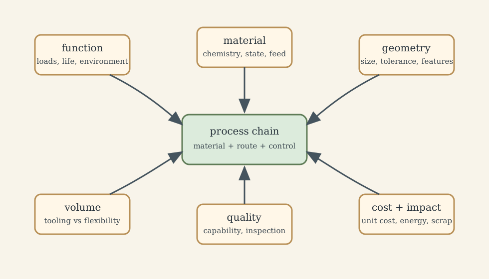
Manufacturing is not just “making a shape.” A manufacturing route is a chain of physical transformations and decisions. Each step reduces one uncertainty while creating another. Refining reduces chemistry variation but creates cost and energy burden. Casting creates near-net geometry but introduces solidification defects. Machining improves precision but may damage the surface layer. Inspection catches variation but cannot recover wasted material. Automation stabilizes repetition but can scale a bad process faster.
The causal spine is:
\[\text{feedstock} \rightarrow \text{process physics} \rightarrow \text{geometry and microstructure} \rightarrow \text{defects and residual stress} \rightarrow \text{inspection and control} \rightarrow \text{assembly} \rightarrow \text{cost, reliability, and sustainability}.\]The engineering question is therefore not “which process is advanced?” It is:
Which material-process-chain can repeatedly meet the functional requirements at the required volume, risk, cost, and traceability?
1. Feedstock: The First Process Window
Manufacturing begins before shaping. Ores, recycled metal, polymer pellets, ceramic powders, composite prepregs, and biomaterial feedstocks already contain variation. That variation may appear later as porosity, viscosity drift, tool wear, weak welds, poor cure, corrosion, or clinical risk.
A robust feedstock specification uses distributions rather than vague names:
- alloy chemistry and impurity limits;
- powder particle size, morphology, oxygen level, and moisture;
- polymer molecular weight, additives, drying condition, and melt-flow behavior;
- ceramic powder agglomeration, binder content, and slurry rheology;
- composite fiber orientation, resin age, tack, and storage history;
- biomaterial cleanliness, passivation state, sterility path, and traceability.
Feedstock quality is not paperwork. It is a predictor of processability. A cheaper incoming material can increase total cost if it widens variation, slows cycle time, damages tools, or forces more inspection. Conversely, a premium feed with tight distributions can reduce scrap and make the process easier to control.
Material and process must be selected as a pair. A casting alloy demanded to behave like a forged fatigue part, or a wrought alloy forced into die-casting economics, creates a hidden contradiction that no amount of inspection can repair.
2. Solidification, Casting, and Molding
Solidification controls geometry, microstructure, and defect inheritance in one event. It appears in metal casting, polymer molding, glass forming, and many additive processes. The mechanism is simple in outline: liquid becomes solid while heat is removed. The consequences are not simple because temperature gradients, shrinkage, solute redistribution, and constrained contraction happen together.
2.1 Freezing Time and Feeding
A useful first estimate for casting solidification is Chvorinov’s rule:
\[t_s = B\left(\frac{V}{A}\right)^n,\]where (t_s) is solidification time, (V/A) is the casting modulus, (B) depends on mold and material conditions, and (n) is often near 2. Thick sections therefore freeze much later than thin sections.
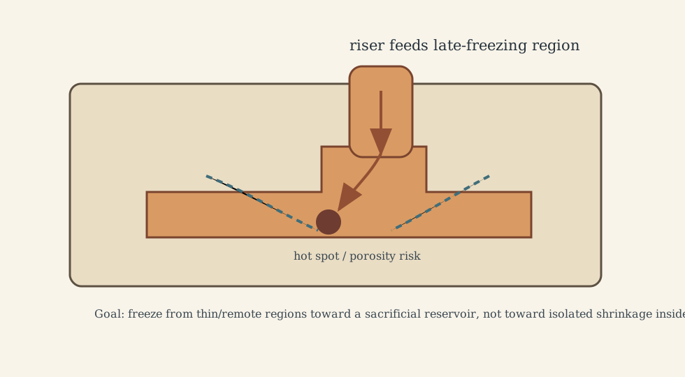
Shrinkage is unavoidable. Porosity is not. The design goal is directional solidification toward a sacrificial riser or reservoir, not random isolated hot spots inside the functional part. Gates manage flow and turbulence; risers manage feeding and shrinkage. Both are thermofluid design elements, not decorative mold features.
2.2 Defects as Mechanism Evidence
Casting defects should be read as evidence:
- shrinkage porosity suggests poor feeding or isolated hot spots;
- gas porosity suggests melt gas, moisture, turbulence, or venting problems;
- cold shuts and misruns suggest insufficient fill temperature, poor flow path, or low fill energy;
- inclusions suggest melt cleanliness, oxide entrainment, refractory erosion, or handling issues;
- residual stress and distortion suggest thermal gradients and constrained contraction.
 Figure 3. Casting process families help map process choice to tooling, tolerance, volume, and defect-control logic. Source: File:Casting_processes.svg. License: CC BY-SA 3.0.

 Figure 4. Solidification conditions showing riser effect and convergent/divergent heat flow in castings. Source: File:Casting_solidification_conditions.svg. License: CC BY-SA 3.0.

2.3 Process Family Tradeoffs
Sand casting is flexible and suitable for large or lower-volume parts, but dimensional spread and surface finish are modest. Die casting offers high throughput and thin-wall capability but has narrow thermal and gas-entrainment windows. Investment casting offers fine detail and high-temperature alloy capability but involves longer cycle time and cumulative shrinkage compensation.
The right choice depends on geometry, alloy, volume, tolerance, defect tolerance, downstream machining, and field reliability. A process that is cheap per pour can become expensive if it creates unstable finishing and inspection loads.
3. Plastic Deformation and Sheet Forming
Deformation processes use plastic flow rather than melting. Forging, rolling, extrusion, bending, stamping, and deep drawing can produce favorable grain flow, high material utilization, and high throughput. The process variable is strain history.
For sheet metal, the central process window is between wrinkling and tearing:
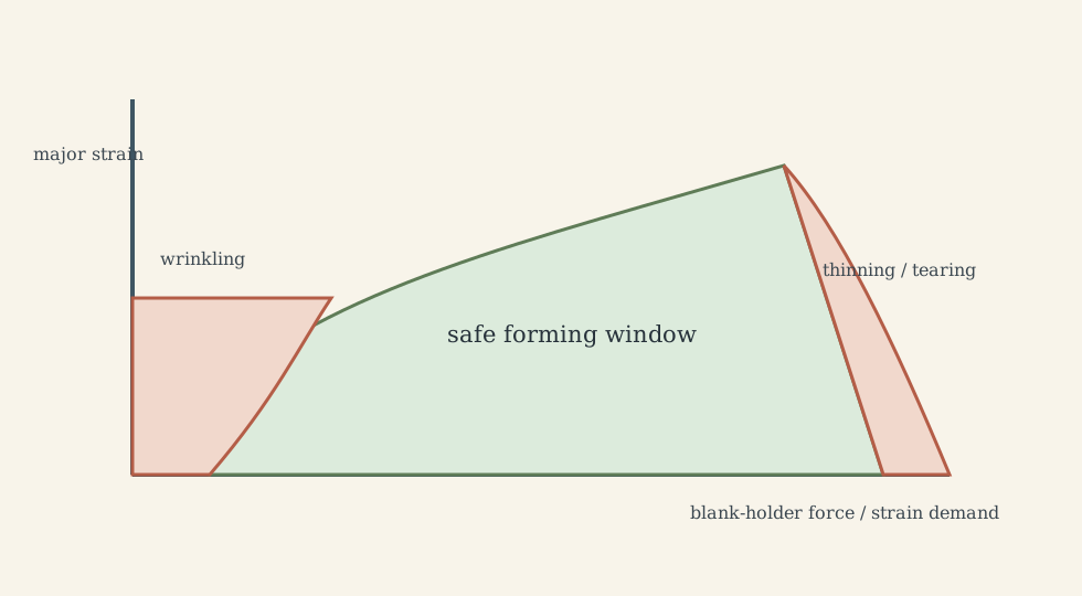
Important levers include:
- blank-holder force;
- friction and lubrication;
- die radius and punch radius;
- draw bead design;
- material anisotropy;
- strain rate and temperature;
- tool stiffness and alignment.
Springback is the elastic part of deformation returning after unloading. It worsens with high-strength materials, thin sections, and low bending stiffness. Die compensation, overbending, restrike operations, warm forming, or stretch control may be needed.
Forging and extrusion can close porosity and align grain flow, improving fatigue performance. But those benefits require stable die fill, thermal control, lubrication, and flash or flow management. A nominally forged part can still fail if folds, laps, decarburization, or poor heat treatment control remain.
 Figure 6. Deep drawing concept showing punch, die, blank, and material-flow constraints. Source: File:Deep_Drawing.svg. License: Public domain.

4. Machining, Surface Integrity, and Dynamic Stability
Machining is often where functional interfaces are made real: bearing seats, sealing faces, bores, threads, precision datums, and assembly surfaces. The goal is not just nominal dimension. It is geometry plus surface integrity.
Chip formation converts mechanical work into heat through plastic shear and friction. If heat leaves mostly with the chip, dimensional and tool stability improve. If heat enters the tool or workpiece, tool wear, built-up edge, thermal expansion, and residual stress become limiting.
Taylor’s tool-life relation is a useful first-order tradeoff:
\[VT^n=C,\]where (V) is cutting speed, (T) is tool life, and (n,C) depend on tool-work material and conditions. It says speed has a nonlinear cost in tool life, but it is not a complete economic model. Real optimization also includes tool-change downtime, scrap risk, machine limits, finishing requirements, and labor or automation context.
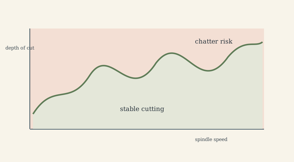
Chatter is a dynamic instability. It raises roughness, accelerates tool wear, and can damage the machine. Stable machining depends on spindle speed, depth of cut, tool holder, workholding stiffness, toolpath smoothness, damping, and controller behavior.
Surface integrity includes:
- roughness and waviness;
- recast or thermally affected layers;
- residual stress;
- microcracks;
- burrs and edge condition;
- contamination from tool or coolant.
Grinding, honing, and lapping are therefore functional operations for sealing, bearing, fatigue, optics, and tribology, not merely cosmetic finishing.
5. Joining: Where Assemblies Often Fail
Most products are assemblies. Joint design often controls system reliability more than base material strength. Joining creates local discontinuities in geometry, material, stress, heat history, and inspection access.
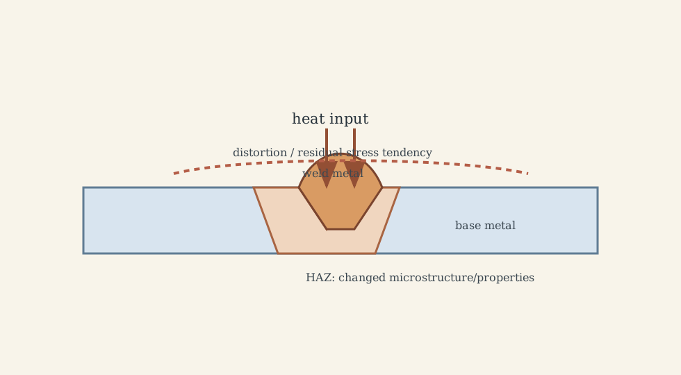
Fusion welding locally melts material. It enables flexible assembly but creates a weld metal zone and heat-affected zone. Microstructure, hardness, residual stress, distortion, and crack susceptibility can change strongly near the joint. Weldability depends on composition, thickness, restraint, cleanliness, hydrogen control, and heat input.
Solid-state joining, such as friction stir welding, avoids bulk melting and can reduce porosity and hot cracking for some materials. It still requires strict control of tool condition, contact force, heat generation, and fixture stiffness.
Adhesive bonding and mechanical fastening are not inferior defaults. Bonding distributes load and can isolate dissimilar materials; fastening supports disassembly and field service. Hybrid joining is often best when stiffness, fatigue, corrosion, repairability, and production rate must all be balanced.
 Figure 9. Typical weld edge preparations and joint preparation logic. Source: File:Welding_edges.svg. License: Public domain.

6. Polymers, Composites, Ceramics, and Biomaterials
6.1 Polymer Processing
Polymer manufacturing is governed by rheology, thermal history, moisture, molecular architecture, and cooling. Injection molding can deliver complex geometry at high volume, but sink, warpage, weld lines, short shots, and burn marks reveal poor filling, packing, venting, or cooling.
Cooling often dominates injection-molding cycle time. Balanced cooling channels, mold temperature control, gate design, and material drying can matter more than simply increasing injection speed. Hygroscopic polymers must be dried because moisture can cause hydrolysis and loss of molecular weight during processing.
Extrusion, blow molding, and thermoforming each control different flow histories. The common rule is that melt preparation and thermal uniformity must be stable before dimensional control can be trusted.
6.2 Composite Manufacturing
Composites gain performance from architecture: fiber orientation, stacking sequence, resin system, and interface quality. That makes them process-sensitive. A small ply-angle error or void population can change stiffness, fatigue life, buckling margin, or impact resistance.
Vacuum bagging and autoclave processing improve consolidation but require vacuum integrity, cure cycle control, and debulk discipline. Resin transfer molding and infusion depend on preform permeability, flow-front timing, and gel-time margin. Pultrusion is efficient for constant-section profiles, but quality depends on pulling speed, die temperature, resin viscosity, and fiber wet-out.
 Figure 10. Pultrusion process flow for continuous composite profile manufacturing. Source: File:Pultrusion_process_01.png. License: Public domain.

6.3 Ceramics and Glass
Ceramics and glass are defect-sensitive because crack-tip plasticity is limited. Powder preparation, agglomeration, binder content, drying, green density, and sintering schedule strongly affect final strength and distortion.
Sintering densifies through diffusion and pore elimination. If heating is too fast, thermal gradients or trapped volatiles create damage. If hold time is excessive, grain growth may reduce desired properties. Glass processing similarly depends on temperature-time profile: annealing reduces residual stress, while tempering intentionally introduces surface compression.
 Figure 11. Tape casting used for thin ceramic layers and substrates. Source: File:Tape_casting.svg. License: CC BY-SA 4.0.

6.4 Biomaterials
Biomaterial manufacturing adds biological compatibility, sterility, regulatory validation, and patient risk. A part can be dimensionally correct but clinically unsafe if surface chemistry, contamination, degradation, or sterilization effects are wrong.
Sterilization is not an afterthought. Steam, gamma, e-beam, and ethylene oxide can affect polymers, coatings, and packaging differently. Traceability, lot genealogy, change control, and validated cleaning are part of the manufacturing process because small uncontrolled changes can alter biological response.
7. Additive Manufacturing: The Print Is Not the Product
Additive manufacturing offers geometric freedom, part consolidation, lattice structures, rapid iteration, and spare-part flexibility. It is not automatically cheaper or more reliable. Production-grade additive manufacturing is a chain:
\[\text{feedstock} \rightarrow \text{build} \rightarrow \text{stress relief} \rightarrow \text{support removal} \rightarrow \text{heat treatment} \rightarrow \text{machining} \rightarrow \text{surface finishing} \rightarrow \text{inspection}.\]In metal powder-bed fusion, steep thermal gradients drive residual stress and distortion. Build orientation, scan strategy, support structure, powder reuse, oxygen level, and chamber conditions influence porosity and anisotropy. Fatigue performance is often limited by surface roughness and internal defects, so post-processing and inspection are central.
Additive should be chosen when it creates system-level value: weight reduction, part consolidation, performance impossible by conventional routes, faster iteration, or supply-chain flexibility. If the part is a simple block with tight tolerances, conventional machining, casting, or forging may still be superior.
 Figure 12. Schematic of laser-based powder-bed additive process architecture. Source: Wikimedia Commons file page for laser powder-bed/sintering schematic. License: CC BY-SA 3.0.
8. Quality: Control Variation Where It Originates
Quality is predictable production over time. End-of-line inspection can sort, but it cannot recover lost material, time, or trust. The stronger strategy is to control variation where it is generated.
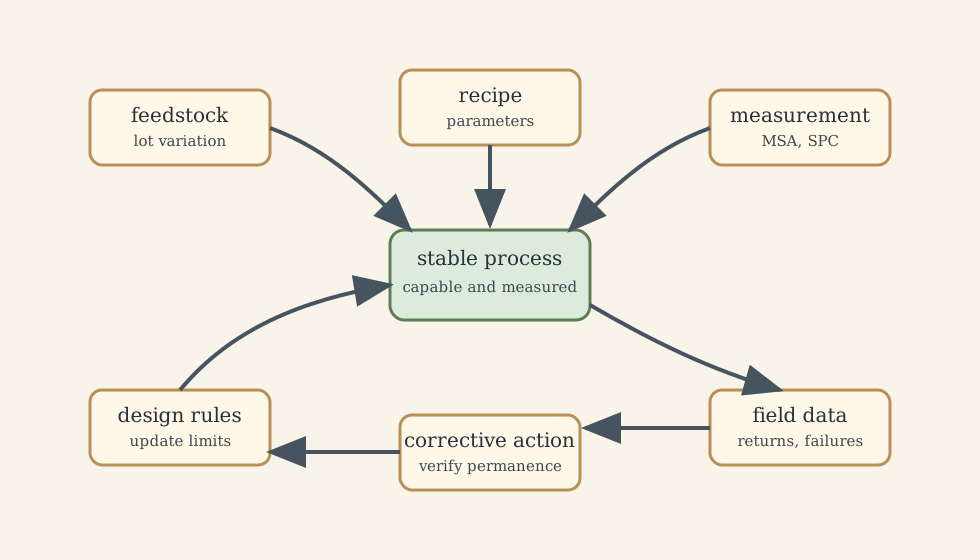
Variation sources include:
- material lots;
- machine dynamics and thermal drift;
- tool wear;
- environment;
- operator method;
- fixture and datum variation;
- measurement noise;
- supplier changes.
Control charts detect changes before specifications are violated, but only if sampling, measurement systems, and reaction plans are credible.
 Figure 14. Example control chart used for process monitoring and early drift detection. Source: File:P_control_chart.svg. License: CC BY-SA 3.0.

Capability indices summarize spread relative to specifications:
\[C_p=\frac{USL-LSL}{6\sigma}, \qquad C_{pk}=\min\left(\frac{USL-\mu}{3\sigma},\frac{\mu-LSL}{3\sigma}\right).\]Here (USL) and (LSL) are upper and lower specification limits, (\mu) is process mean, and (\sigma) is standard deviation. These metrics are useful only when the process is stable and the measurement system is trustworthy. Measurement System Analysis is therefore not optional if capability numbers drive decisions.
Root-cause analysis must be mechanism-based. Five-why and fishbone diagrams are scaffolds; physical evidence, process data, metrology, and repeat verification decide whether the cause was real.
9. Automation, CNC, Robotics, and Digital Threads
Automation should be understood as variation control and throughput stabilization, not simply labor substitution. CNC, robots, sensors, and digital manufacturing systems create value when they reduce drift, increase traceability, shorten reaction time, and keep humans away from hazardous work.
CNC performance depends on toolpath design, workholding, machine dynamics, look-ahead, jerk limits, thermal stability, and cutting data governance. Robots depend on end-effector design, part presentation, sensing, calibration, and cell-level safety. A robotized cell with unstable upstream variation may perform worse than a disciplined manual cell.
Digital manufacturing threads connect CAD, CAM, MES, quality databases, maintenance systems, and supplier data. The goal is not dashboards; the goal is faster, more reliable decisions:
- which recipe changed?
- which lot is affected?
- which tool created the suspect surface?
- which measurement system drifted?
- which field failures map to which process window?
Predictive maintenance is useful only when sensing is contextualized by recipe, tool, material, and machine state. Blind alarms create fatigue; decision-specific signals create value.
10. Manufacturing Economics and Sustainability
Manufacturing cost is system cost. It includes tooling, cycle time, yield, inspection, rework, maintenance, inventory, energy, scrap, warranty exposure, and changeover.
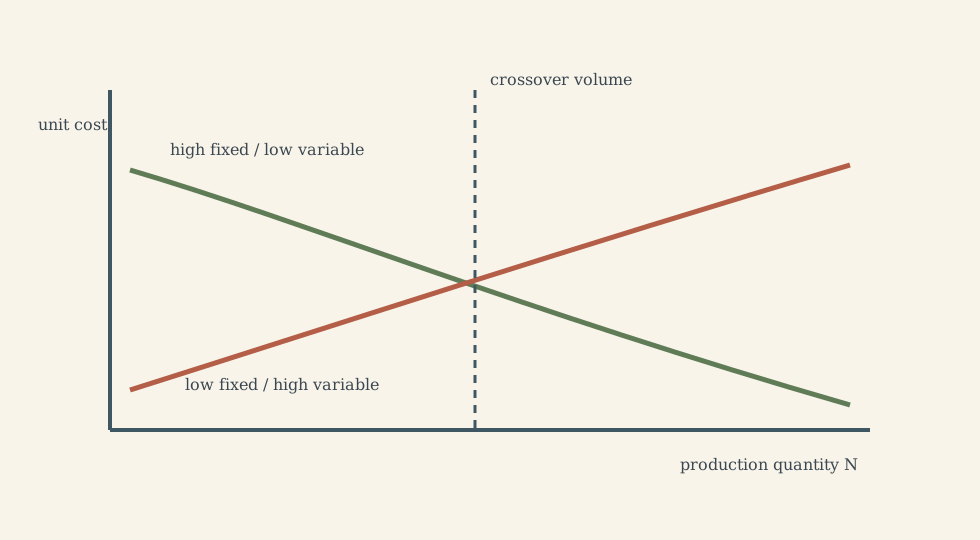
The simplest volume relation is
\[C_{unit}=\frac{C_F}{N}+C_V,\]where (C_F) is fixed investment, (N) is production quantity, and (C_V) is variable cost per unit. High-tooling processes often win at high volume; flexible low-tooling processes often win during prototyping or uncertain demand.
Sustainability is now an engineering constraint, not a marketing label. Energy intensity, material yield, coolant use, emissions, scrap recovery, repairability, remanufacturing, and recyclability all affect process selection. Near-net shape, durable tooling, closed-loop material recovery, and design-for-disassembly can reduce environmental and economic cost together.
11. Integrated Example: Combustion-Engine Manufacturing
Combustion-engine production is a compact example because it combines casting, forming, machining, heat treatment, joining, coating, assembly, metrology, cleanliness, and statistical control.
Engine blocks and cylinder heads are often cast near-net shape, then machined at functional interfaces: bores, bearing saddles, gasket faces, oil passages, and mounting datums. Casting quality affects machining allowance and porosity risk; machining affects sealing, friction, and assembly stack-up. Cranktrain parts often rely on forging, heat treatment, grinding, and surface integrity because fatigue margins dominate.
Final assembly adds torque strategy, cleanliness, sealant behavior, leak testing, and poka-yoke controls. Failures often come from cumulative small deviations rather than one dramatic mistake. The general lesson is:
robust products are created by coherent process chains, not isolated excellent steps.
What This Framework Lets Us Do
This framework lets us read a manufacturing route as a controlled transformation:
- what material state enters each step?
- what mechanism changes geometry or properties?
- what defects can be created?
- what signal reveals drift early?
- what control action is realistic at production speed?
- what downstream step inherits the variation?
- what cost or sustainability tradeoff replaces the current bottleneck?
It also helps avoid process-name thinking. “Casting,” “machining,” “welding,” and “additive” are not answers. The answer is a process chain with controlled mechanisms and measured capability.
Where the Framework Stops Being Reliable
This note is a high-level engineering map. Real manufacturing decisions require material-specific data, tooling design, supplier capability, machine limits, safety regulations, environmental rules, and pilot-run evidence. A process that is robust for one alloy, polymer grade, part size, or volume can fail when those boundary conditions change.
Where the Subject Leads Next
Manufacturing connects naturally to:
- materials science and failure analysis;
- CAD/CAM, FEM, and CFD process simulation;
- operations management and production planning;
- quality engineering and measurement systems;
- robotics, CNC, and industrial automation;
- lifecycle engineering, sustainability, and circular manufacturing.
Technical and Editorial Audit
| Area | Correction or decision |
|---|---|
| Central question | Reframed manufacturing as controlled transformation under physics, quality, cost, and sustainability constraints. |
| Preserved material | Retained core coverage of feedstock, solidification, casting, forming, machining, joining, polymers, composites, ceramics, biomaterials, additive manufacturing, quality, automation, economics, and engine integration. |
| Equations | Kept Chvorinov’s rule, Taylor tool-life relation, capability indices, and unit-cost relation; added variable meanings and limits. |
| Figures | Preserved useful existing external process figures and added seven original SVG decision/mechanism diagrams. |
| Defects | Reorganized defects by mechanism rather than process-name lists. |
| Practical limits | Emphasized pilot evidence, measurement-system validity, process capability, and chain-level cost. |
| Internal links | Recommended future links to materials, CAD/CAM/FEM/CFD, operations management, robotics/automation, and quality-related notes. |
Main Sources Used in This Note
- CityU MNE3119 course material.
- Existing Wikimedia Commons figures cited inline with their file pages and licenses.