Engineering Drawing, CAD/CAM, FEM, and CFD - From Geometry to Analysis
This note is adapted from course materials for MNE2116 Engineering Graphics, MNE3007 CAD/CAM, and MNE4005 Finite Element Analysis at City University of Hong Kong. Instructors: Prof. Weiyin MA and course teaching staff.
Central Question
How do engineers turn design intent into unambiguous geometry, manufacturable instructions, and credible simulation evidence without losing the meaning of the part?
Engineering drawing, CAD, CAM, FEM, and CFD are not separate islands. They are representations of the same product under different questions:
\[\text{intent} \rightarrow \text{drawing definition} \rightarrow \text{CAD geometry} \rightarrow \text{CAM process} \rightarrow \text{FEM/CFD model} \rightarrow \text{validation} \rightarrow \text{revised design}.\]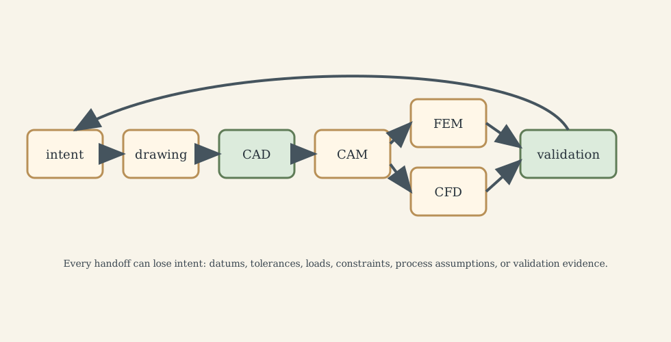
1. Drawing: Geometry as a Human-Readable Contract
A drawing is not a picture. It is a controlled technical statement. Orthographic projection removes perspective distortion so dimensions, alignments, sections, and datums can be read consistently.
Important drawing decisions:
- choose first-angle or third-angle projection and show the symbol;
- select views that reveal the functional geometry;
- use section views for internal features;
- dimension each feature once;
- attach tolerances to functional requirements, not habit;
- define datums before geometric tolerances;
- avoid crowded sheets that make interpretation ambiguous.
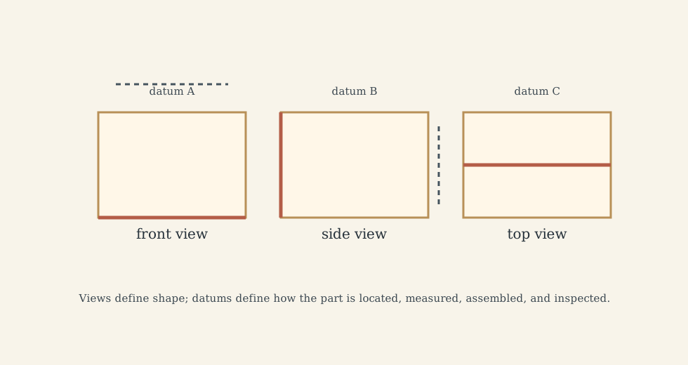
The core risk is ambiguity. If two machinists, inspectors, or suppliers can read the same drawing differently, the drawing is not yet an engineering contract.
2. CAD: Geometry as a Computable Model
CAD stores geometry and topology in a form software can evaluate. Sketches, constraints, features, surfaces, solids, assemblies, and parametric histories are all modelling choices. The model should encode intent:
- dimensions that represent design variables;
- constraints that preserve relationships;
- features ordered to support later edits;
- assemblies that represent interfaces and motion;
- simplified configurations for simulation and manufacturing.
Curves and surfaces such as Bezier, B-spline, and NURBS representations are useful because they make shape mathematically controllable. Solid modelling matters because downstream operations need closed volumes, valid topology, and consistent normals.
Bad CAD is not merely ugly. It creates unstable toolpaths, broken meshes, unclear assemblies, and unreliable revisions.
3. CAM: Geometry as Machine Action
CAM converts geometry into setups, fixtures, tools, toolpaths, feeds, speeds, approach moves, retract moves, and NC code. A CAM plan is a manufacturing hypothesis:
\[\text{part geometry} + \text{stock} + \text{fixture} + \text{tool} + \text{machine limits} \rightarrow \text{controlled material removal}.\]Key questions:
- which datums locate the part?
- can the tool reach the feature?
- what stock remains after each operation?
- where are collision and gouging risks?
- what tolerance is produced by the process, not just requested by the drawing?
- how do tool deflection, chatter, heat, and wear affect final geometry?
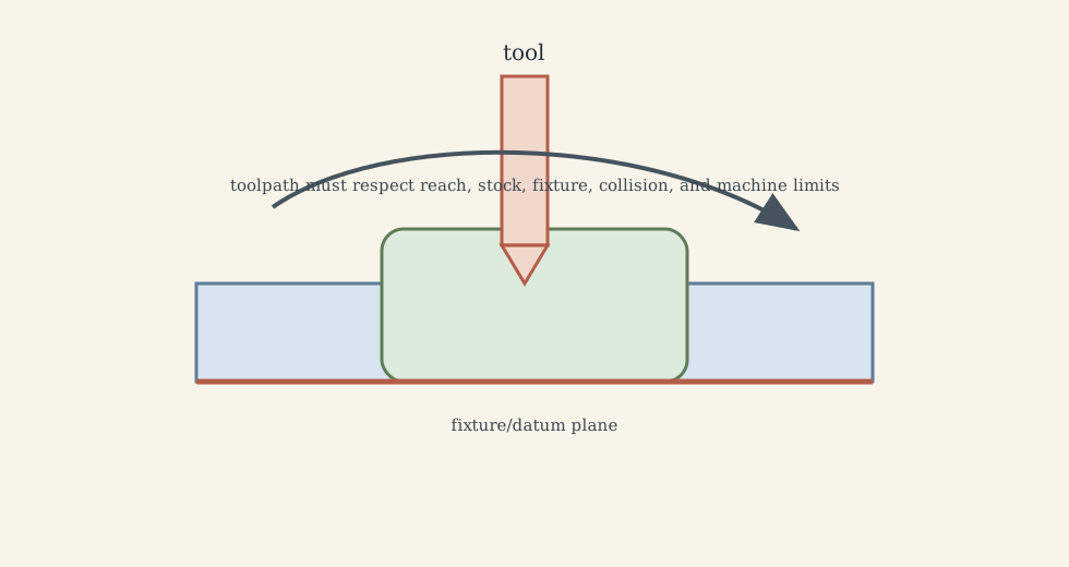
Simulation inside CAM is useful, but it verifies the programmed path under model assumptions. It does not prove the real fixture, tool, material, or machine will behave ideally.
4. FEM: Geometry as a Discrete Structural Model
Finite element analysis approximates continuum behavior by dividing a domain into elements. The conceptual chain is:
\[\text{CAD domain} \rightarrow \text{idealized analysis geometry} \rightarrow \text{mesh} \rightarrow \text{materials, loads, constraints} \rightarrow \text{solution} \rightarrow \text{verification and validation}.\]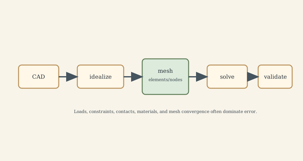
The most common FEM mistake is treating a colorful stress plot as truth. A credible model must state:
- what geometry was suppressed;
- which material law was used;
- where loads and constraints come from;
- whether contact, plasticity, thermal stress, or dynamics matter;
- whether the mesh is converged near stress gradients;
- whether singularities are physical or modelling artifacts;
- what experiment or hand calculation bounds the result.
For linear static elasticity, the compact system is
\[K u = f,\]where (K) is global stiffness, (u) is nodal displacement, and (f) is load vector. That compact equation hides the entire modelling responsibility.
5. CFD: Geometry as a Flow Domain
CFD models the fluid domain, not the solid part by default. The first decision is therefore domain definition:
- internal flow or external flow?
- inlet/outlet boundaries far enough away?
- wall roughness and thermal condition?
- laminar, transitional, or turbulent regime?
- incompressible or compressible?
- steady or unsteady?
- conjugate heat transfer needed?
The governing equations are conservation of mass, momentum, and energy. The mesh, boundary conditions, turbulence model, and numerical scheme determine what is actually solved.
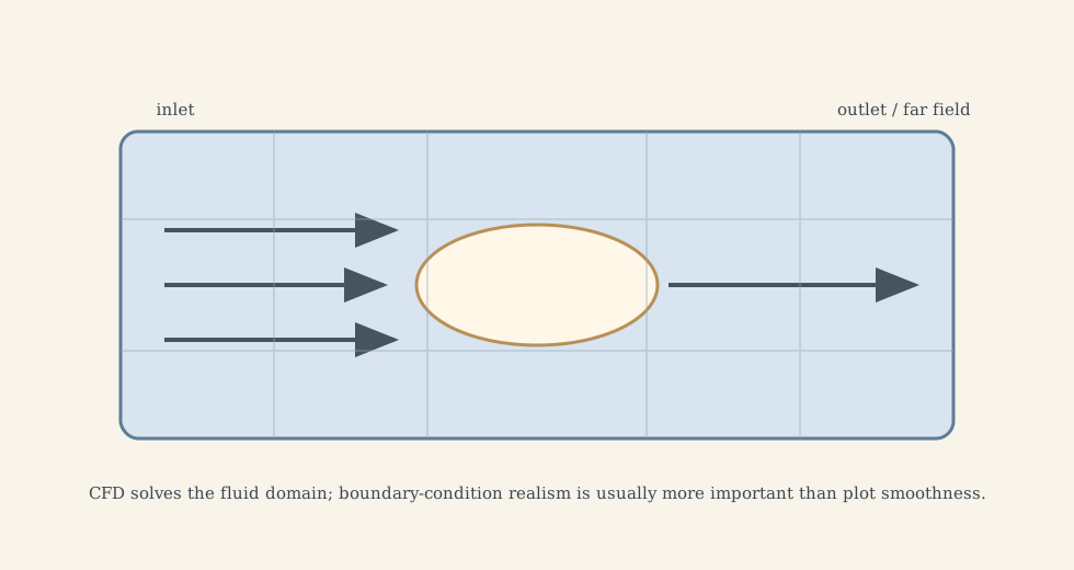
CFD results should be checked against conservation balances, grid sensitivity, known limiting cases, and measurements. A smooth streamline plot can still be wrong if the boundary condition is wrong.
6. Translation Risks Across the Workflow
Each handoff can lose meaning:
- drawing to CAD: dimensions become geometry but manufacturing notes may be lost;
- CAD to CAM: design geometry becomes stock-removal sequence;
- CAD to FEM: fillets, holes, contacts, and constraints are idealized;
- CAD to CFD: the solid body becomes a fluid boundary;
- simulation to design: a numerical field becomes a decision.
The safe habit is to ask what each representation must preserve: functional surfaces, datums, tolerances, interfaces, loads, flow paths, material state, manufacturing allowances, or inspection features.
What This Framework Lets Us Do
It lets us treat engineering geometry as an information pipeline rather than a software sequence. The practical skill is preserving intent while changing representation.
Where the Framework Stops Being Reliable
The framework fails when the representation is trusted outside its assumptions: ambiguous drawings, fragile CAD, unverified CAM, unconverged FEM, unvalidated CFD, or simulation loads that do not match service reality.
Where the Subject Leads Next
This workflow leads to geometric dimensioning and tolerancing, model-based definition, manufacturing process planning, finite element verification, CFD validation, digital twins, and product lifecycle management.
Technical and Editorial Audit
| Area | Correction or decision |
|---|---|
| Central question | Reframed the note around preserving engineering intent across representations. |
| Preserved material | Kept drawing, projection, CAD, CAM, FEM, and CFD coverage while condensing long procedural detail. |
| Equations | Kept the core FEM system (Ku=f) and emphasized assumptions behind it. |
| Figures | Added five original SVG diagrams for the representation pipeline, drawing/datum logic, CAM setup, FEM idealization, and CFD domain setup. |
| Validation focus | Emphasized ambiguity, mesh convergence, boundary conditions, and physical validation. |
Main Sources Used in This Note
- CityU MNE2116, MNE3007, and MNE4005 course material.