Fluid Dynamics Notes
This note is adapted from course materials for MNE3122 Fluid Mechanics and MNE4201 Aerodynamics at City University of Hong Kong. Instructors: course teaching staff.
Central Question
How do mass, momentum, energy, viscosity, pressure, vorticity, compressibility, and boundaries determine how fluids move and what forces they exert?
Fluid dynamics is conservation law plus regime judgment. The same equations cover creeping microflows, pipe networks, aircraft wings, blood flow, pumps, weather, nozzles, and shocks, but different terms dominate in different regimes.
\[\text{system boundary} \rightarrow \text{conservation laws} \rightarrow \text{dimensionless groups} \rightarrow \text{dominant balances} \rightarrow \text{models/correlations} \rightarrow \text{forces, losses, and validation}.\]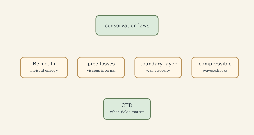
1. Conservation Laws
Mass conservation is
\[\frac{\partial \rho}{\partial t}+\nabla\cdot(\rho\mathbf{u})=0.\]For incompressible flow, (\rho=\text{constant}), so
\[\nabla\cdot\mathbf{u}=0.\]Momentum conservation for a Newtonian incompressible fluid with constant viscosity is
\[\rho\left(\frac{\partial\mathbf{u}}{\partial t}+\mathbf{u}\cdot\nabla\mathbf{u}\right) =-\nabla p+\mu\nabla^2\mathbf{u}+\rho\mathbf{g}.\]Energy becomes necessary when temperature, compressibility, combustion, or heat transfer matters:
\[\rho c_p\left(\frac{\partial T}{\partial t}+\mathbf{u}\cdot\nabla T\right) =k\nabla^2T+\Phi+\dot q'''.\]The nonlinear convective acceleration term (\mathbf{u}\cdot\nabla\mathbf{u}) is why exact solutions are rare and why turbulence, separation, and vortex shedding are hard.
2. Regime Selection
Dimensionless groups tell us which physics dominates:
| Group | Formula | Meaning |
|---|---|---|
| Reynolds | (Re=\rho UL/\mu) | inertia / viscosity |
| Mach | (Ma=U/a) | speed / acoustic speed |
| Froude | (Fr=U/\sqrt{gL}) | inertia / gravity |
| Prandtl | (Pr=\nu/\alpha) | momentum diffusion / heat diffusion |
| Peclet | (Pe=RePr) | advection / heat diffusion |
| Strouhal | (St=fL/U) | unsteadiness / convection |
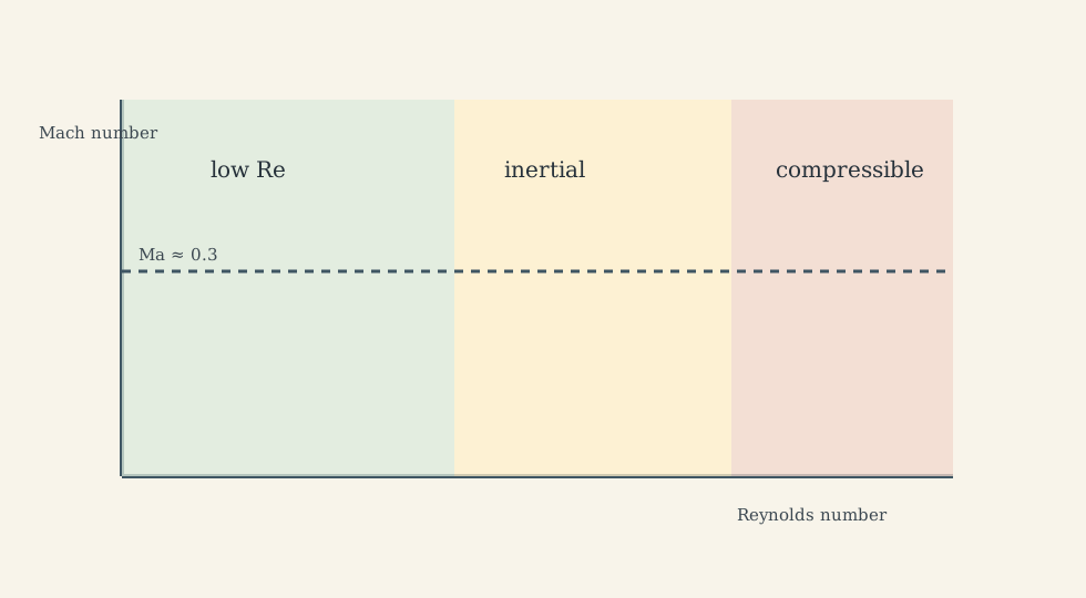
Regime mistakes are expensive. Bernoulli fails in separated, highly viscous, or strongly unsteady regions. Incompressible models fail when density variation matters. Laminar correlations fail in turbulence. CFD fails when the boundary conditions or turbulence model are wrong.
3. Statics, Bernoulli, and Mechanical Energy
For a fluid at rest,
\[\frac{dp}{dz}=-\rho g, \qquad p=p_0+\rho gh\]for constant-density liquids. Buoyancy is
\[F_B=\rho_f g V_{\text{displaced}}.\]For steady, incompressible, inviscid flow along a streamline,
\[\frac{p}{\rho g}+\frac{V^2}{2g}+z=\text{constant}.\]Real pipe systems add machines and losses:
\[\frac{p_1}{\rho g}+\alpha_1\frac{V_1^2}{2g}+z_1+h_p = \frac{p_2}{\rho g}+\alpha_2\frac{V_2^2}{2g}+z_2+h_t+h_L.\]Bernoulli is not a magic pressure-speed slogan. It is mechanical energy conservation under restrictive assumptions.
4. Viscous Flow, Boundary Layers, and Losses
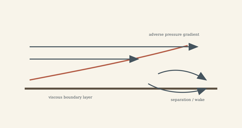
Viscosity diffuses momentum. At high (Re), viscosity may be negligible in the outer flow but remains decisive near walls and in wakes.
Pipe losses are commonly represented by Darcy-Weisbach:
\[h_f=f\frac{L}{D}\frac{V^2}{2g}.\]The friction factor (f) depends on Reynolds number and relative roughness. Minor losses from bends, valves, entrances, and exits are often written
\[h_m=K\frac{V^2}{2g}.\]The engineering task is to account for all relevant loss mechanisms without pretending correlations are universal constants.
5. Lift, Drag, and Aerodynamics
Aerodynamic forces are usually nondimensionalized:
\[C_L=\frac{L}{\frac12\rho V^2S}, \qquad C_D=\frac{D}{\frac12\rho V^2S}.\]Lift comes from pressure and shear integrated over the body, not from one isolated story. Circulation, pressure field, angle of attack, boundary-layer state, and separation all matter.
Drag includes:
- skin-friction drag;
- pressure/form drag;
- induced drag from finite wings;
- wave drag in transonic/supersonic regimes.
Stall occurs when adverse pressure gradient and separation destroy the attached-flow lift mechanism. Airfoil data are therefore regime data: Reynolds number, Mach number, surface roughness, and turbulence level matter.
6. Compressible Flow, Shocks, and Nozzles
Compressibility matters when density changes couple to motion, often for (Ma\gtrsim0.3). The speed of sound for an ideal gas is
\[a=\sqrt{\gamma RT}.\]For isentropic ideal-gas flow,
\[\frac{T_0}{T}=1+\frac{\gamma-1}{2}Ma^2.\]Nozzles reveal the key compressible-flow surprise: a converging-diverging nozzle accelerates subsonic flow in the converging part, reaches (Ma=1) at the throat if choked, and accelerates supersonically in the diverging part.
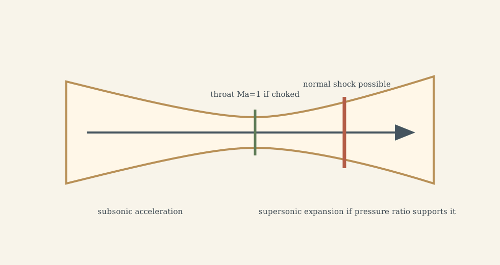
Shocks are thin irreversible compression waves. Across a shock, pressure, temperature, density, and entropy rise, while Mach number drops. Shocks are not numerical artifacts; they are physical consequences of compressible nonlinear conservation laws.
7. CFD and Experimental Validation
CFD solves discretized conservation laws. It is powerful only when the model choices match the flow:
- domain and boundary conditions;
- mesh resolution and wall treatment;
- turbulence or transition model;
- compressibility and heat-transfer assumptions;
- time step and convergence criteria;
- comparison to experiment or limiting theory.
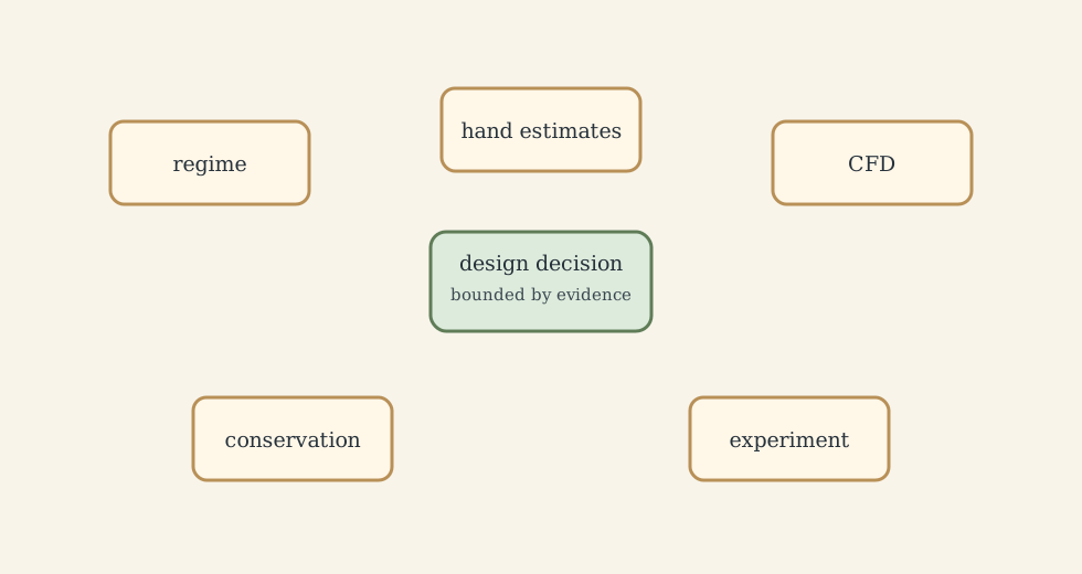
Good fluid engineering triangulates: hand estimates set scale, CFD resolves fields, experiments reveal reality, and conservation checks catch nonsense.
What This Framework Lets Us Do
It lets us choose the right simplification: hydrostatics for rest, Bernoulli for ideal mechanical energy, pipe correlations for internal viscous losses, boundary-layer theory for wall effects, compressible relations for high Mach, and CFD when geometry/regime complexity requires field simulation.
Where the Framework Stops Being Reliable
It fails when regime assumptions are wrong: high (Ma) treated incompressibly, separated flow treated inviscid, turbulence treated laminar, cavitation ignored, multiphase flow simplified as single-phase, or CFD used without validation.
Where the Subject Leads Next
Fluid dynamics leads to aerodynamics, turbomachinery, combustion, heat transfer, ocean/atmospheric flows, biomedical flows, CFD, and flow control.
Technical and Editorial Audit
| Area | Correction or decision |
|---|---|
| Central question | Reframed fluid dynamics around conservation laws and regime selection. |
| Preserved equations | Kept continuity, Navier-Stokes, energy, hydrostatics, Bernoulli, pipe losses, lift/drag coefficients, speed of sound, and isentropic stagnation relation. |
| Figures | Added five original SVG diagrams for model hierarchy, regime map, boundary layer separation, nozzle/shock logic, and validation loop. |
| Key correction | Emphasized assumptions behind Bernoulli, correlations, compressibility thresholds, and CFD. |
Main Sources Used in This Note
- CityU MNE3122 and MNE4201 course material.